 Disjoncto


Electrical
Single-line diagram
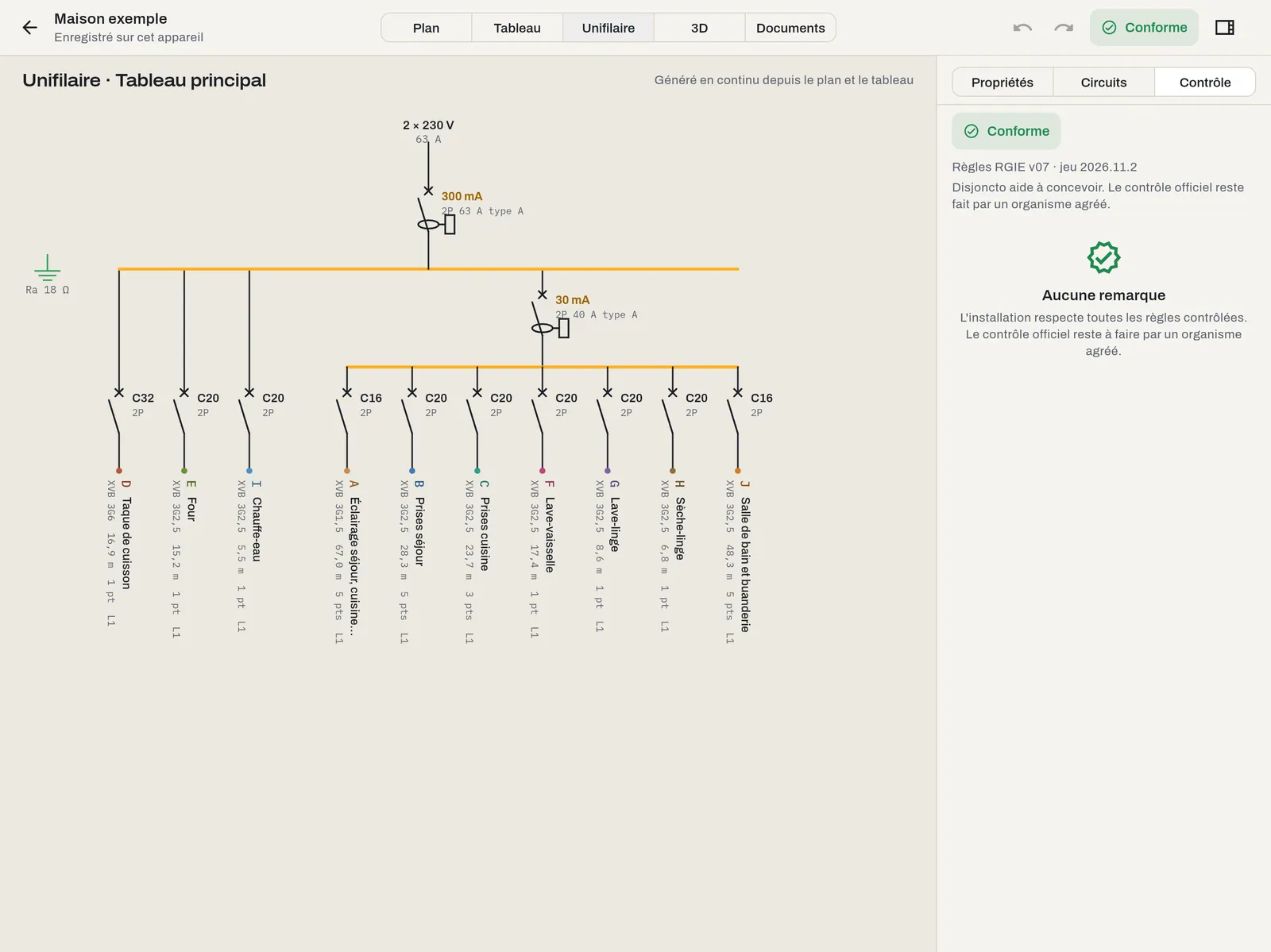
Single-line mode (key 3) draws the board diagram from the model. There is nothing to draw: it follows every change.
Contents#
From top to bottom: the supply (network and voltage), the main RCD with its sensitivity and type, the busbar, the 30 mA RCDs and the circuits they protect, then one outgoing line per circuit: circuit breaker with curve and rating, and, in vertical text, the reference, the description, the cross-section, the cable length and the number of points. The earth electrode and its resistance appear on the left. The colours are those of the circuits on the plan; an element carrying a remark is flagged.
Reading and navigation#
Pinch or use the wheel to zoom (from 30% to 400%), drag to pan. With several boards, choose the board from the list at the top. When the number of circuits changes, the diagram redraws with a short drawing animation.
Changing the diagram#
The diagram is not edited directly: change the circuit (Circuits tab or board module), the RCD hierarchy (Board mode) or the points (Plan mode). The single-line diagram follows.
In the file#
The “Single-line diagram” sheet reproduces this diagram, one per board, in landscape with the title block. See Documents.