 Disjoncto


Electrical
Circuits
A circuit groups points behind one protective device. Disjoncto can distribute everything according to the rules, then you adjust by hand.
Automatic distribution#
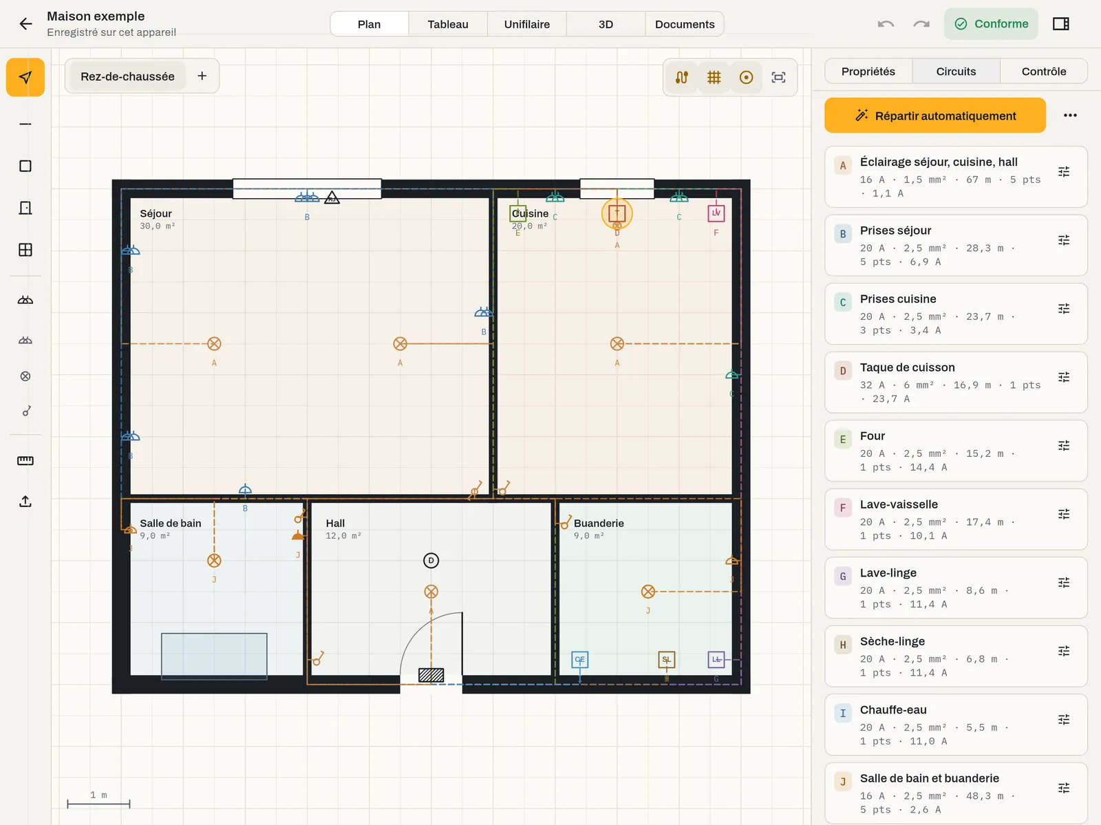
In the Circuits tab, the Distribute automatically button (or “Distribute n points” if some points still have no circuit) assigns the points that do not yet have a circuit. Existing circuits are left untouched. The order followed:
- If the board has no main RCD, a 300 mA RCD is added.
- Appliances needing a dedicated circuit (hob, oven, washing machine, tumble dryer, dishwasher, water heater, EV charger, heat pump, air conditioner, solar inverter, 32 A socket): one circuit each, with the cross-section and rating of the dedicated circuits rule, behind a 30 mA RCD of the required type when the appliance demands it or sits in a wet room.
- Wet rooms: the other points in the bathroom or shower room, on a 2.5 mm² · 16 A mixed circuit behind a 30 mA RCD.
- Sockets: first those in the kitchen, then the others, grouped by room, 8 points at most per circuit, in 2.5 mm² · 20 A.
- Lighting: grouped by room, 8 points at most per circuit, in 1.5 mm² · 16 A.
- The remaining points join socket circuits; controls follow the ceiling lights they control.
With the v07 rule set, lighting and socket circuits are also placed behind a 30 mA RCD. A 30 mA RCD protects at most 8 circuits; beyond that, a new one is created. Circuits are named after their contents (“Living room sockets”, “Lighting living room, kitchen, hall”, “Hob”).
The ⋯ menu offers Recalculate all: all the circuits on the board are recreated according to the rules, after confirmation. In three-phase, it also offers Rebalance phases, and L1, L2, L3 bars show the power per phase in kW. Both actions can be undone.
Manual assignment#
- One point: the Circuit list in its properties.
- Several points: multiple selection, then Assign to circuit.
- In both cases, New circuit… creates the circuit and its circuit breaker on the main board.
The check reruns at once: moving a hob onto a socket circuit brings up the dedicated circuits remark.
The circuit list#
Each line shows the reference, the name (or the type), then the rating, the cross-section, the cable length (followed by * if set manually), the number of points and the estimated current. An icon flags the circuit's worst status. Tap a line to highlight the circuit on the plan; tap it again to turn the highlight off.
The settings button opens the circuit: Name, Circuit type (Lighting, Sockets, Dedicated circuit, Mixed, Control), Cross-section (1.5 to 35 mm²), Rating (6 to 63 A), Curve (B, C, D), Phase (L1; in three-phase L2, L3 or L1 L2 L3), Cable (XVB/XGB, VOB in conduit, EXVB, XFVB) and Length set manually. Delete removes the circuit and its circuit breaker; its points are left without a circuit.
References and point numbers#
As the RGIE requires (Book 1, 3.1.2.1.a), each circuit gets a capital letter: A, B, C… then AA, AB… beyond Z. The letter appears under each symbol on the plan once the zoom is sufficient, on the modules and labels of the board, in the single-line diagram and in the documents. The points of a circuit are numbered from the protective device (A1, A2…); displaying these numbers on the plan and in the documents is coming soon.
Cables routed along the walls#
For each circuit, Disjoncto draws the cable from the board and chains the points along the shortest path following the walls of the level, then adds the vertical drops: via the ceiling for points at 1.20 m or higher, 30 cm above the floor for the others. The length includes 30 cm of slack per point and a 10% allowance. Cables are shown as dashed lines in the circuit colour; the Cables button (C) hides them. The board is positioned with the Board symbol on the plan.
This length is used for the voltage drop calculation and the cable list in the file.
Manually set length#
If the real run differs (conduit, another floor, a detour), enter the length in Length set manually. The help under the field reminds you of the calculated length; clear the field to return to the automatic calculation. A manually set length is marked * in the list.